How to get accurate 3D scans from a GoPro
Methodology for handling fisheye camera lenses to produce extremely accurate 3D mountain bike models
09/08/2026
By Matthew Hilton

This post assumes you know about photogrammetry and fisheye lenses like those found on a gopro. Please check out my previous 2 articles the power of a gopro and what is DirtScan to find out more.
An important puzzle piece to this project is create an accurate 3D scan - after all, the whole point was to avoid the GoPro effect that plagues mountain bike Youtube videos.
As with most things in life, this is much easier said than done.
On a theoretical level, if you had a perfect understanding of a fisheye lens and it’s optics, and had perfect super high resolution images (with no motion blur, rolling shutter, etc.) you would be able to produce a perfect model.
While we’re not looking for perfect here, it does need to be as close as possible. The bar I set for myself is that over 1km, it is allowed to drift by < 1m. This might sound easy, but because mountain bike trails are long paths that never (or rarely) cross over themselves, this goal actually requires the camera at each step to be extremely accurate in its position as otherwise it would cause the whole chain after it to be misaligned.
Issue #1 - Camera calibration
Let’s start with some off-the-shelf photogrammetry software, say Agisoft’s Metashape.
If we dump a bunch of photos into it and tell it to process it (setting the Camera type in Metashape to fisheye), you will notice that subsequent runs produce different models, for example:
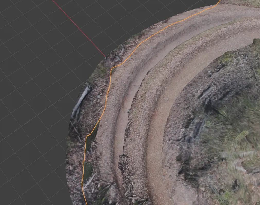
This is the same berm, but from two different scans. What happened here? Part of the answer is camera calibration.
There is no ‘perfect’ mathematical equation that tells you how to undo fisheye distortion, but there are some that exist that are fairly close. The one Metashape uses has various parameters, which if you do not specify them, Metashape will try and guess:
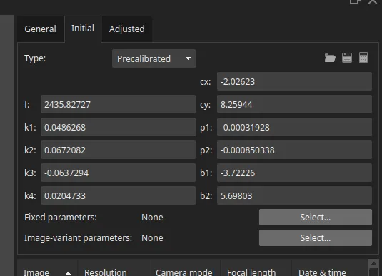
Metashape does its best to guess to give you something, but it is almost certainly not accurate (which is fair, not everyone needs accuracy so I understand why they do this).
For those who do care about accuracy - Metashape includes a checkboard calibration procedure. This uses a printed, flat checkerboard that it can use to model the intrinsics.
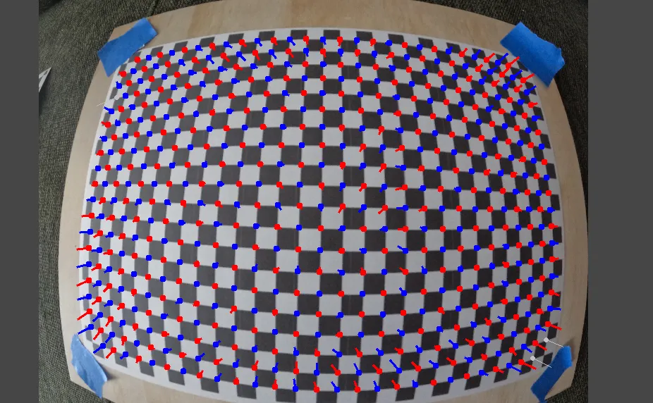
Using this, you can then “lock” the calibrated parameters. This usually solves a lot of error, but not all.
Issue #2 - Parralax
A mountain bike trail is a long straight line. I tried for a long time to make the process simply be to walk down a trail once (as this saves time + is simpler). Doing this, however, was not feasible as it did not produce enough parralax. Parralax is the change of position of something in a photo, when looking at it from a different viewpoint.
In our case, if you imagine walking straight down a trail looking forwards, most objects are almost static between frames. They just become “bigger” by tiny amounts every frame.
I have mostly solved this issue by using the following trail scanning technique:
- Walk down a trail, holding the GoPro in my right hand (because i’m right handed) looking around 45 degrees to my left.
- After N photos, I turn around and walk back down the same section but now the other direction, still holding the GoPro in my right hand looking around 45 degrees to my left.
The combination of holding the GoPro not straight but angled produces more parralax, and the forward + back views also produce a lot of views of objects from vastly different angles. This reduces the error even further.
Issue #3 - Reference object
Even with the most accurately calibrated fisheye lens model we can get, it is still not going to be perfect. This means we need an external reference - something to keep it grounded.
Normally most would gravitate towards GPS here. However, GPS will actually make it worse! This is because GPS is not as accurate as you think, it can often have errors of 1-10 metres. For a good reference we need centimeters, not metres of error.
Instead, the way to do this is with a scale bar. A scale bar is just a reference object you include in the photos/scans that is of a known size. I’ve gone through various iterations of scale bars, testing each for their usability, durability, ease of construction, and importantly - accuracy.
What I landed upon was a 1m square steel tube, with 3x plastic pieces bolted onto it, and 3x APRILtags. An APRILtag is just like a low-resolution QR code, which can be very accurately detected from a long distance away. I chose to use steel over wood because it is extremely rigid (I previously had issues with wood scale bars warping/wobbling and also blowing over in the wind because they were too light!). All of this costs < $20 from Bunnings.
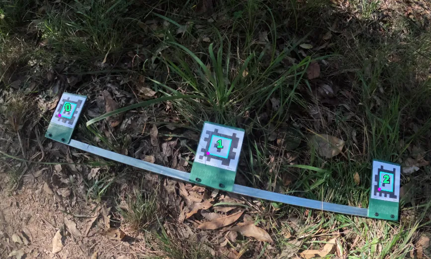
Because each tag is a known size (80mm), and the distance between each tag is known, the photogrammetry software can compare and adjust its position/triangulation of the scene
Confirming accuracy
Traditionally this would have to be done via a really expensive, high accuracy GPS system. In our case, however, we are lucky. State and local government conduct aerial lidar surveys, i.e. they scan the ground from a plane using very expensive equipment. For my purposes, I am assuming this is the “ground truth”. These scans are advertised as 1 metre accuracy, which means we can actually see the faint imprint of a mountain bike trail on the scan.
These are gathered from ELVIS - In my area, the Brisbane City Council and the Moreton Bay Regional Council both have Digital Elevation Model (DEM) data with 1M accuracy.
For example here, is Jurassic at Bunyaville Conservation Park - you can see the road, the footpath, and the slight imprint of the start of the trail.
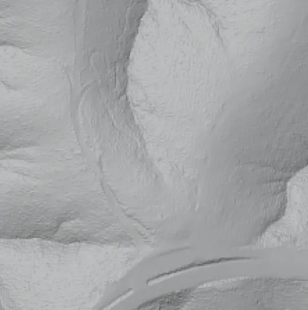
Using this, we can compare out trail path to the DEM to check how well it went.
It’s important to note, these aerial scans are only done every 10 years or so, meaning:
- It is not always exactly the same - trails can be realigned or changed
- New trails will not show up as they were not built at the time of the scan.
This is why I purposely only use the DEM to reference/check the output - I do not feed it in as a data point into the program otherwise this process would not work on new or changed trails.
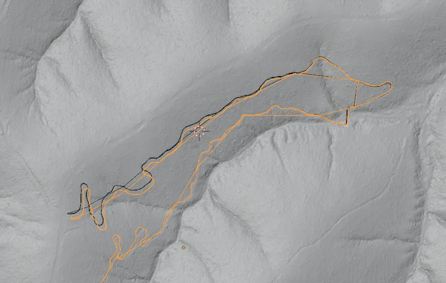
Even if a 3D scan is good for some of the trail, does not mean it is good for all of the trail, for example here is a scan of the Jurassic trail at Bunyaville Conservation Park, which was good for about 3/4 of the run but the last 1/4 had an unexpected bow/error causing the end of the trail to be misaligned by about 3-4 metres (this was with an older version of my process).
The proof
Given this, how accurate have I got it so far? Does my process actually work?
Here is a reference scan I did at Toohey forest, which over around a 1.1km segment was able to align nearly perfectly with the 1m DEM. I’m sure it is not 100% perfect, but I think it easily passes my goal of having < 1m of error over 1km of trail.
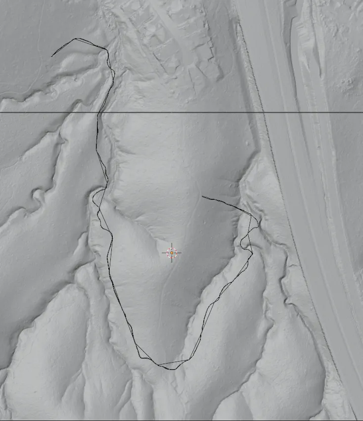
Note, Toohey forest trails are not technically mountain bike trails, but structurally for this test they are identical. I only did it at Toohey as it is fairly quiet; eventually this will be done on an actual trail!
Conclusion
I purposely did not get too technical in this post. Once the code mature from the “hacky prototype” stage I will release it, and it will become the source of truth for the exact method, requirements, and tradeoffs.
Given the accuracy has achieved my goal, I’m now working on the next steps in the process (generating the 3D model from this camera path, and texturing it, and all the issues that come along with that!)